PRODUCTS
Existing system overview:
Worldwide are number of ships equipped with PLC based Boiler & Burner Management Systems, which use PLC equipment for which manufacturer announced discontinuation of production and spare parts.Ships boiler system needs solution for which is possible to get spare parts and technical support in time. To help customer with above problem we will design system which can retrofit present old type PLC solutions.
Design goal
System must be designed in a way to:
– ensure flexible expanding of the configuration according to the target original system,
– support expansion options for the ECR outstation,
– data exchange with SBS-ACC systems, and data visualization
– password protection for the upload /download of the program
– password protection for the Know How Protection of the program blocks
– password protection for the commissioning settings screens
– PLC supplier Siemens
SBS-BSC-1
Custom made for a one-to-one retrofit product; the SBS-BSC-1 is the perfect retrofit solution for the Saacke FOSA Controller in the market. Approved by DNV-GL on its design and software, the SBS-BSC-1 is 26% smaller installation footprint in comparison to FOSA, with no adjustment of software or parameters, and case-to-case project upgrade approval process needed. A bliss in installation makes easy for any ship’s electrician or SBS Service Engineer.
There’s more!
The SBS-BSC-1 provides:
• A standard temperature range of hardware up to 60°C.
• An extended temperature range versions of hardware up to 70°C.
• Allowance for Horizontal or vertical installation positions.
• A relative allowed humidity of up to 95% during operation with no condensation.
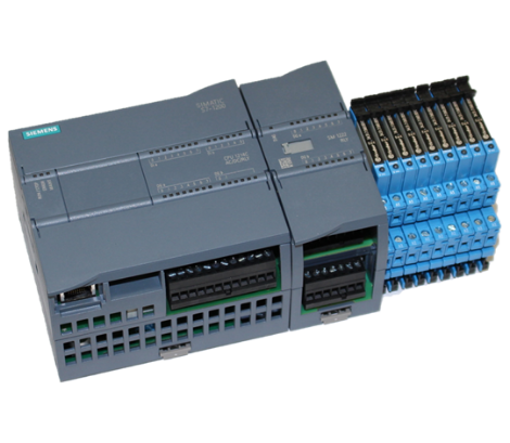
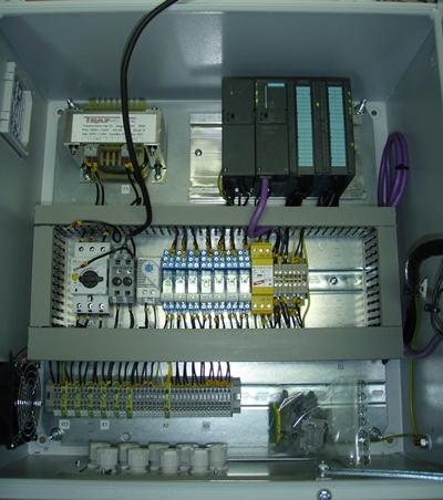
System Components
The System consists of:
1. N1 – Siemens S7 1200 PLC Unit (14 digital inputs/10 relay outputs).
2. N2 – Siemens Relay output module (16 relay outputs).
3. Auxiliary relays (9 relays).
Determine for yourself and request for a consultation with one of our experts to find out more!
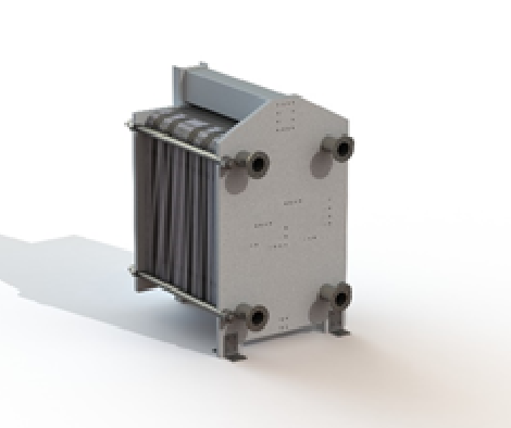
TEPU
Power Pack
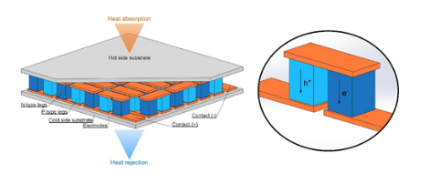
Introducing SBS Engineering’s Thermo Electrical Power Unit that works its magic on a powerful principle. Using Peltier semiconductor elements use heat flux to generate DC currents. This is done by condensing surplus steam using cooling water. The switch gear will then transform the DC output to AC matching the vessel grid to perform its function.
Benefits
The Thermoelectrical Generator is the waste heat that provides free and non-polluting power resulting in: 1. Fuel Consumption and Carbon Footprint Reduction 2. SEEMP (Ship Energy Efficiency Plan) Improvement 3. Auxiliary Diesel Engine overhaul intervals Extension
Operationally, you get to enjoy:
1. Zero moving parts
2. Maintenance Costs Reduction
3. Stepless and 100 % flexible configuration
4. Reliable and proven switch gear
More Payback
Enjoy even more payback with our TEPU!
1. Lower cost of electricity at US$90/MWh for our TEPU as compared to US$200/MWh for a diesel generator
2. Simplified Payback Period of less than 2.2 years based on reduced wear of Aux. Diesel engines
3. Service life expectancy 20+ years
4. Very low or no maintenance costs
Pick up our brochure today and speak to one of our consultants for more details!
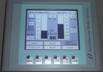
Monitoring functions:
Solutions based on the Feedback Manipulation Unit ensures that systems which are not designed to run on dual fuel (HFO & LS MGO) have additional Fuel/Air curve for the MGO operation, ensuring optimum performance on both fuels.
Nozzle Pressure (Analog Input 0) -in Bargraf form & in Real number value
Burner Flow (kg/h) (Analog Input 1 OR tacho signal Digital Input 0.0)
-in Bargraf form & in Real number value, this filed can be hiden if commissioning engineer want to have all adjustment done in the l/h.
Burner Flow (l/h) (Analog Input 1 OR tacho signal Digital Input 0.0)
-in Real number value, this ensures that we can see if we have correct input signal before calculation is performed into kg/h.
Indication of the Selected Fuel:
-HFO / MGO type of the fuel is selected, for this there is 2 field with text for indication
AIR RATIO input field
-ensures end user to be able to lineary make correction to the output +/- 20%
IGNITION FORCING AO Pressure
-This is used for indication that until Main Oil Valves are opened, Nozzle pressure is forcing as a analog output from the SBS-FMU unit. This is used on some systems which are checking that i.e. Nozzle pressure must be over 10kg/cm2 before opening of the Main Oil Valves. This option can be Enabled/Disabled in the Settings 4 screen and also delay alarms can be adjusted.
OUTPUT Type of forward signal
-This is indicating if current output is forward of FLOW or PRESSURE signal. Ensuring that commissioning engineer has information of the real output signal.
Alarm & Indication functions:
BACKFIRE Protection – Flow
-monitor that during MOV Opened (DI0.7) Flow thru nozzle is less then Sepoint Value in time interval defined in the Settings page. Value can be adjusted in the Settings screen. For which you need password.
BACKFIRE Protection – Pressure -monitor that during MOV Opened (DI0.7) Pressure of nozzle is less then Sepoint Value in time interval defined in the Settings page. Value can be adjusted in the Settings screen. For which you need password.
SBS-ACC-1B
SBS ACC 1B, Automatic Combustion Control One Boilers
Solutions based on the Automatic Combustion Controller ensures that systems which are not designed to run on dual fuel (HFO & LS MGO) have additional Fuel/Air curve for the MGO operation, ensuring optimum performance on both fuels. This is mainly used when present controllers are obsolete and this is installed as retrofit ensuring availability of spare parts in future.
Combustion Control System Description
A fuel-air metering control system is essential for efficient combustion in boilers, furnaces, and other large fuel-fired heating processed. These systems vary in complexity from the simple metered approach to the complex cross-limiting system, which is used to ensure safe firing during load changes.
SBS-ACC-1B is build on SIEMENS S7-313C PLC and SIEMENS KTP 600DP Basic Touch screen hardware platform and SIEMENS S-7 programming software. All calculations in software are done using representation of analogue input in %. Physical unit of measurement are fused for indication purposes only. F.O flow feedback signal can be of Analogue current (4-20mA) Flow meter or Press (indirect flow measurement) signal and Tacho (frequency) signal selectable in system configuration.
It comprises of following functions:
– Fuel flow controller
– Air flow controller
– Ignition, Purge, FO recirculation & Burner firing positions selection over digital inputs, parameters for each mode configurable over HMI
– 2 F/A curves (switching via fuel selection Digital inputs )
– F/A Ratio control
– Fuel temperature monitoring (different set points for MGO/HFO, activated with F.O. Type selection)
– Alarming and registration of alarm events in Alarm History
– Fuel & Air Controller Trends
SBS ACC 3B, Automatic Combustion Control Three Boilers
Same as ACC-1B but for boilers with up to 3 burners installed on 1 boiler. These are very complex systems and we managed to offer retrofit solution for obsolete Gaudelius & Shimadzu controllers, which are expensive and hard to get.
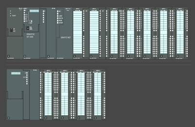
Combustion Control System Description
A fuel-air metering control system is essential for efficient combustion in boilers, furnaces, and other large fuel-fired heating processed. These systems vary in complexity from the simple metered approach to the complex cross-limiting system, which is used to ensure safe firing during load changes.
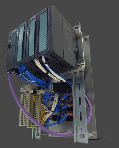
SBS-ACC-3B is device to control fuel oil and combustion air for optimum combustion, so that steam pressure may be kept at the set pressure at all time for required steam flow. System is build on SIEMENS S7-313C PLC, SIEMENS analogue input module SM331 2xAI, SIEMENS analogy output module SM332 4xAO, and SIEMENS KTP 600DP Basic Touch screen hardware platform and SIEMENS STEP7 programming software.
All calculations in software are done using representation of analogue input in %. Physical unit of measurement are fused for indication purposes only. F.O flow feedback signal can be of Analogue current (4-20mA) Flow meter or Press (indirect flow measurement) signal and Tacho (frequency) signal selectable in system configuration.
It comprises of following functions:
– Fuel flow controller
– Air flow controller
– Ignition, Purge, FO recirculation & Burner firing positions selection over digital inputs, parameters for each mode configurable over HMI
– 2 F/A curves (switching via fuel selection Digital inputs )
– F/A Ratio control
– Fuel temperature monitoring (different set points for MGO/HFO, activated with F.O. Type selection)
– Alarming
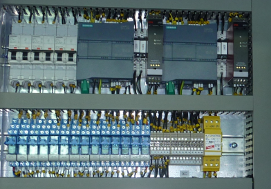
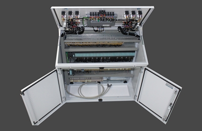
SBS-BBMS, Boiler & Burner Management System
Represents Boiler & Burner Management System, which is integrated system for the: sequence, combustion, water level controllers, master-slave operation, alarm and monitoring,… Our solution is designed to retrofit obsolete PLC?s for which on the market is hard to get spare parts and support. All components are type approved by major marine classification societies, and our development of software is conducted according to the ISO 9001 and ISO 90003 guidelines. Our solution also offers Boiler Mimic Panel To ensure that our retrofit solution will be for the crew very familiar and ensures that they will very easily operate it.
System is based on the Siemens SIMATIC PLC and Siemend KTP1000 Touch panel, with marine approval. System is very modular and retrofit any automation type of equipment, either old PLC systems or solutions based on Controllers and relays.
Functional parts inside BBMS software:
-Sequencer-MGO/HFO operation
-MC (Master Controller)
-FOC (Fuel Oil Controller)
-AIRC (Air Controller)
-WLC (Water Level Controller)
-Alarm processing page-Monitoring of process values
-Purging time adjustable-Post-Purging time adjustable
-Double set of the PID parameters
-Steaming up
-Master / Slave option
-Tanker Service / Eco / IGS mode of operation
-Automatic operation of Boiler
-Manual operation of Boiler
-Feed Water pumps control block
-Fuel Oil pumps control block
-Oxygen Analyzer monitoring
-Smoke Analyzer monitoring
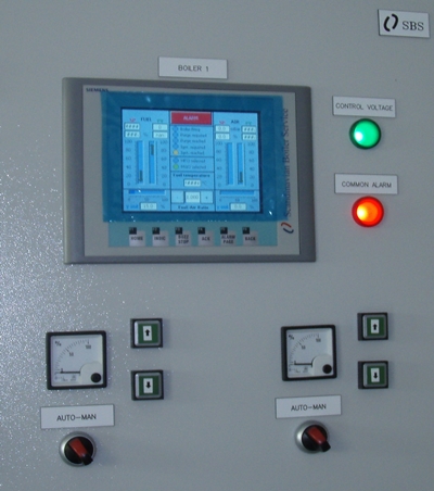
General description of the control system
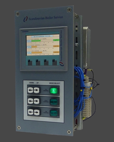
Auto/manual station is analog output equipment which, in case of programmable analog controller (PAC) self-diagnosed an irreversible error, replaces PAC. Auto/manual station can freely increase and decrease analog output values. Auto/manual station is a follow-up type, which maintains and controls the last output value of PAC prior to the switch-over.
Specification
Auto/manual station has 10 digital inputs, 5 digital outputs, 8 analog input (0/4-20mA, 0-10V, 1-5V), 4 analog outputs (0/4-20mA, 0-10V, 1-5V) and touch panel with 4 function keys (MAIN, INDIC, ALARM and BACK) and 9 additional key for operation.
Main functions
1. Auto/manual mode of each Analog Input signal is switched by way of key operations, and their current modes can be confirmed on Touch screen.
2. Increase and decrease of each analog input can be controlled and put out separately.
3. Pac output value is put on hold at the time emergency output becomes OFF
4. Output values can be displayed real-time in digital or bar graph.
5. Cause of alarm is displayed
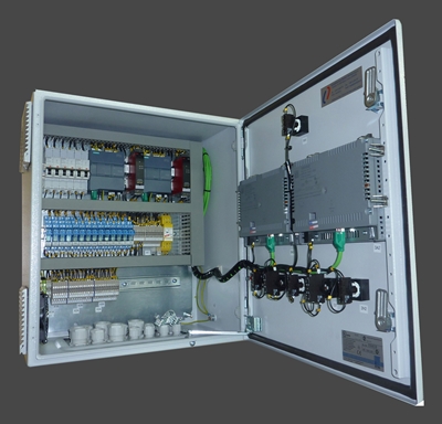
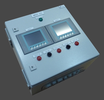
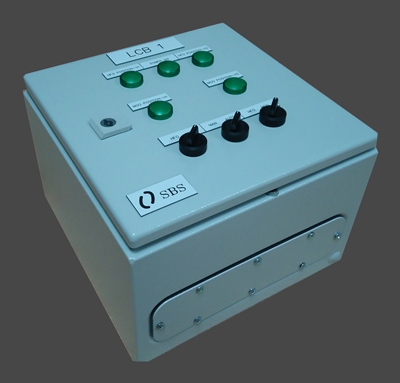
+MGO CC, Marine Gasoline Oil Control Cabinet
Solutions based on the FMU product, which are installed and prewired, so we save time on commissioning.
– Equipment certificated by all mayor classification companies: DNV, BV, ABS, LLoyd, DNV
– Upgrade of system to Flow feedback, using Kral Volumeter proven for many years in boiler systems
– Additional Fuel/Air curve inside SBS-FMU, no need to upgrade existing ACC in the BCP (Boiler Controll Panel)
– Easy to commision, so saving time needed for commissioning
– Flow feedback signal selection between pick up & 4-20mA transmiter
– HFO operation Pressure feedback forwarding as before
– MGO operation Flow feedback forwarding but manipulated over Fuel/Air table
– Advanced Boiler protection:
1) Flow too hi shutdown (En/Dis)
2) MGO temperature Hi Alarm
3) Backfire protection (for Pressure feedback)
4) Backfire protection (for Flow feedback)
5) Wrong sprayer selection blocking & indication
– System aplicatible to all Boilers with positioners
– Dimensions: 500 x 500 x 300mm
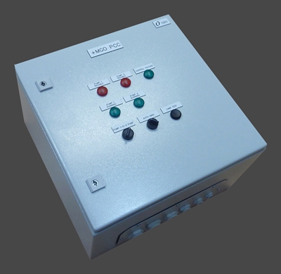
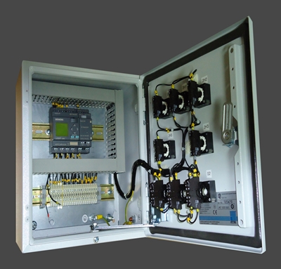
+MGO PCC, Marine Gasoline Oil Pumps Control Cabinet
Are Pump Control Cabinets designed to ensure full automatic operation of the boiler system on both fuels.
– Equipment certificated by all mayor classification companies: DNV, BV, ABS, LLoyd, DNV
– Automatic stop of the pump during standby of the boiler
– Automatic change over of the pumps
– Indication of fault states
– Counting of the operational hours
– Manual & Automatic operation
– Easy to commision, so saving time needed for commissioning
– Dimensions: 500 x 500 x 300mm
Pictures are sample and can vary from project to project!
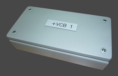
+MGO VCB, Marine Gasoline Oil Valves Connection Box
– Equipment certificated by all mayor classification companies: DNV, BV, ABS, LLoyd, DNV
– Dimensions: 300x150x80 mm
Pictures are sample and can vary from project to project!
+MGO VCC, Marine Gasoline Oil Valves Control Cabinet
– Equipment certificated by all mayor classification companies: DNV, BV, ABS, LLoyd, DNV
– Automatic change over with calculated blending time
– Indication of positions
– Easy to commision, so saving time needed for commissioning
Pictures are sample and can vary from project to project.
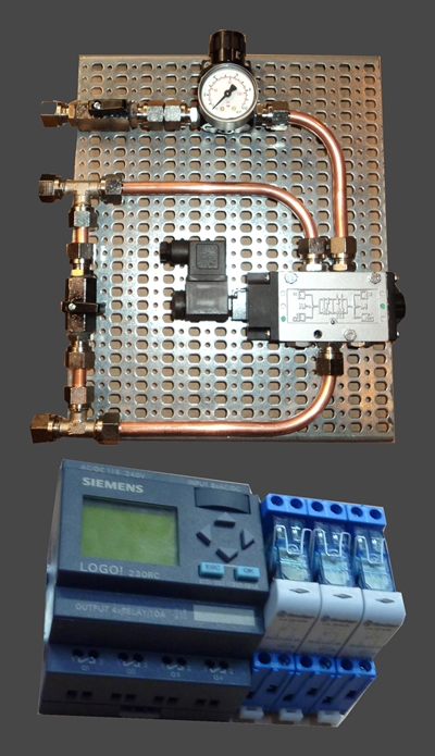
+MGO EmPostPurge, Marine Gasoline Oil Emergency Post Purge System
System is designed to ensure post purging in case of Flame failure during burner operation in Emergency mode. To avoid adding of new control element in Combustion Air damper control loop (4-20 mA from ACC) pneumatic solution is chosen for control during post purging in Emergency operation.
System consists of:
PLC & relays
PLC is monitoring burner mode of operation (auto/emergency), status of Main oil valves and both Flame scanners.
Pneumatic
Opening of Combustion air damper via solenoid valve V1 to position determined with Press regulator R1.
Valve V1 is spring return and in normal position air from damper I/P positioner is directed to control drive, when V1 energized air adjusted on press regulator R1 is forwarded to control drive.
For bypassing of pneumatic system V2 (control air shutoff) shell be closed and V3 (solenoid bypass) opened.
PLC (Siemens LOGO 230 RC) is powered from 230 VAC source permanently to avoid PLC start-up time at power-up (if connected to EMG. Operation power supply, certain time will be necessary for PLC to load program and establish RUN mode).
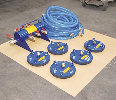
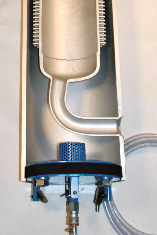
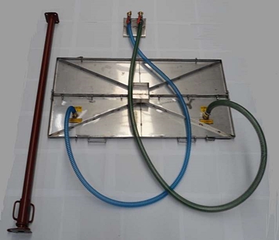
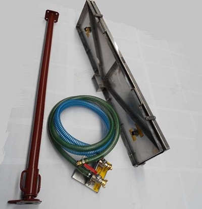
SBS PinClean
Unique Cleaning Device for Pin Tubes – Cleanse with the Power of Bubbles
Scandinavian Boiler Service is presenting the new SBS PinClean™. The SBS PinClean™ is the most suitable cleaning device for all oil fire boilers, composite boilers, etc. with pin tubes in the combustion chamber.
SBS Cleaning Plugs
SBS Cleaning Device for Uptake
In many composite or oil-fired boilers, the convection part consists of water tube uptake. These boilers are designed to have a high flue gas velocity through the tube nest in order to keep the tubes clean and efficiency high. If soot deposits are accumulated on the tube surface, this will result in less convection heat transferred to the water/steam, thus decreasing the efficiency of the boiler. Normally, this is shown as higher flue gas temperature and increasing pressure loss over the boiler.
Flame failure can occur because of back pressure from furnace room depending on the amount of flow that can pass inside the tubes. It is impossible to give an exact interval for when the tube nest should be cleaned as this depends on various factors such as oil quality, burner adjustments and operation load of the boiler. A visual inspection frequently inside the boiler is a good and most reliable method to check if cleaning of tube nest is necessary. It is always easier to maintain than to clean when the tubes are already blocked.
SPEAK TO OUR EXPERTS
With a network of global offices, SBS is always ready to answer the call of duty from our clients worldwide. We would love to hear from you, be it a service call or general enquiries.