PROJECTS & RETROFITS
Introduction
Our engineering division excels in preparing for larger upgrades and conversions. Design, calculations, and modification drawings are conducted by our experienced engineers to ensure smooth execution procedures, they are in close contact with our service engineers, ensuring real feedback from the process field and giving us the advantage to develop systems that are user friendly and can provide better performance.
SBS is providing engineering solutions that can use equipment from different manufactures and for different manufacturers of boiler systems.
We are specialized in the development of software solutions for PLC based systems and industrial controllers. All of which are conducted according to the ISO9000:2008 and guidelines ISO90003:2004.
Our range of services also includes making electrical drawings, and project management.
The development of highly productive boiler systems is characterized by the demand for high availability and an increase in the functionality and degree of automation. This leads to increased complexity, particularly with regard to the software for activating, coordinating, and monitoring the individual machine functions. Managing the complexity requires interdisciplinary cooperation between the various departments involved in development.
PROJECT ENGINEERING
Complexity engineering
Developing software for modern machine tools is becoming more difficult because of the increasing functionality and resulting complexity. An approach for managing this is provided by the model-driven development of the control software. However, this innovative development method requires both a procedure that is adapted to the specific application domain and suitable modeling techniques. The article describes an approach appropriate for machine tools. The focus is on introducing the necessary description techniques and a methodology for their use in product development.


SOFTWARE DEVELOPMENT
Model-driven development
Concurrent engineering requires the use of modern development methods and redesign of established procedures. While model-supported static and dynamic design of the machine structure through the use of methods is already widely used, model-based development of machine tool control software has not yet caught on in the real world. This is particularly true for PLC software, which implements bosh technological and safety-related functions. The reason for this include the late integration of software engineering into machine development and the unavailability of suitable development tools.
Waste Heat Recovery Economizer after Auxiliary Engines
Auxiliary engine waste heat has not been considered in the past, but it contains a large amount of energy. The energy that can be utilized supplementing steam requirement during the port stay and – for some vessels – also during the voyage. This significantly helps reducing oil consumption on the oil-fired boiler.
To ensure the most advantageous design, the economizer will be tailor-made to the individual ship and engine specification with due consideration of existing uptake, back pressure, etc. The economizer is produced in two designs, one requiring steam space in another boiler (e.g. in an existing boiler) and one that has its own steam space.
This new product will provide operational savings while improving the green image and environmental profile of the ship and the company.
Waste Heat Recovery


COMBUSTION CONTROL RETROFITS
Combustion Process
The most common fuels consist of carbon and hydrogen. Combustion is the rapid oxidation,
i.e., rapid combination with oxygen, of a fuel release heat. Stoichiometric, or perfect, combustion combines the exact proportions of fuel and oxygen to obtain complete conversion of the carbon and hydrogen to yield water vapor, carbon dioxide, and heat. The ideal proportions of fuel and air vary directly with the BTU content of the fuel. Too much air results in energy losses up the stack. Insufficient air results in loss of heat generation due to incomplete fuel combustion.
A certain amount of excess air is required to ensure that complete combustion occurs within the combustion chamber and to compensate for delays in fuel-air ratio control action during load changes.
The purpose of the combustion control system is to maintain constant steam pressure at the super heater outlet header for all loads by varying the rate of combustion in boiler furnaces. The control also maintains the proper ratio of fuel and air at all rates of combustion.
To change the steaming rate, the automatic combustion control must adjust the following:
1. Fuel oil to the furnace
2. Combustion air to the furnace
Monitoring functions:
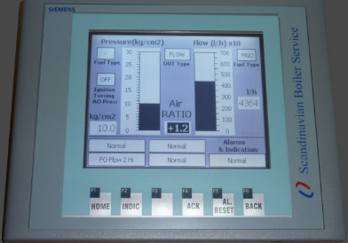
Solutions based on the Feedback Manipulation Unit ensures that systems which are not designed to run on dual fuel (HFO & LS MGO) have additional Fuel/Air curve for the MGO operation, ensuring optimum performance on both fuels.
Nozzle Pressure (Analog Input 0) -in Bargraf form & in Real number value
Burner Flow (kg/h) (Analog Input 1 OR tacho signal Digital Input 0.0)
-in Bargraf form & in Real number value, this filed can be hiden if commissioning engineer want to have all adjustment done in the l/h.
Burner Flow (l/h) (Analog Input 1 OR tacho signal Digital Input 0.0)
-in Real number value, this ensures that we can see if we have correct input signal before calculation is performed into kg/h.
Indication of the Selected Fuel:
-HFO / MGO type of the fuel is selected, for this there is 2 field with text for indication
AIR RATIO input field
-ensures end user to be able to lineary make correction to the output +/- 20%
IGNITION FORCING AO Pressure
-This is used for indication that until Main Oil Valves are opened, Nozzle pressure is forcing as a analog output from the SBS-FMU unit. This is used on some systems which are checking that i.e. Nozzle pressure must be over 10kg/cm2 before opening of the Main Oil Valves. This option can be Enabled/Disabled in the Settings 4 screen and also delay alarms can be adjusted.
OUTPUT Type of forward signal
-This is indicating if current output is forward of FLOW or PRESSURE signal. Ensuring that commissioning engineer has information of the real output signal.
Alarm & Indication functions:
BACKFIRE Protection – Flow
-monitor that during MOV Opened (DI0.7) Flow thru nozzle is less then Sepoint Value in time interval defined in the Settings page. Value can be adjusted in the Settings screen. For which you need password.
BACKFIRE Protection – Pressure -monitor that during MOV Opened (DI0.7) Pressure of nozzle is less then Sepoint Value in time interval defined in the Settings page. Value can be adjusted in the Settings screen. For which you need password.
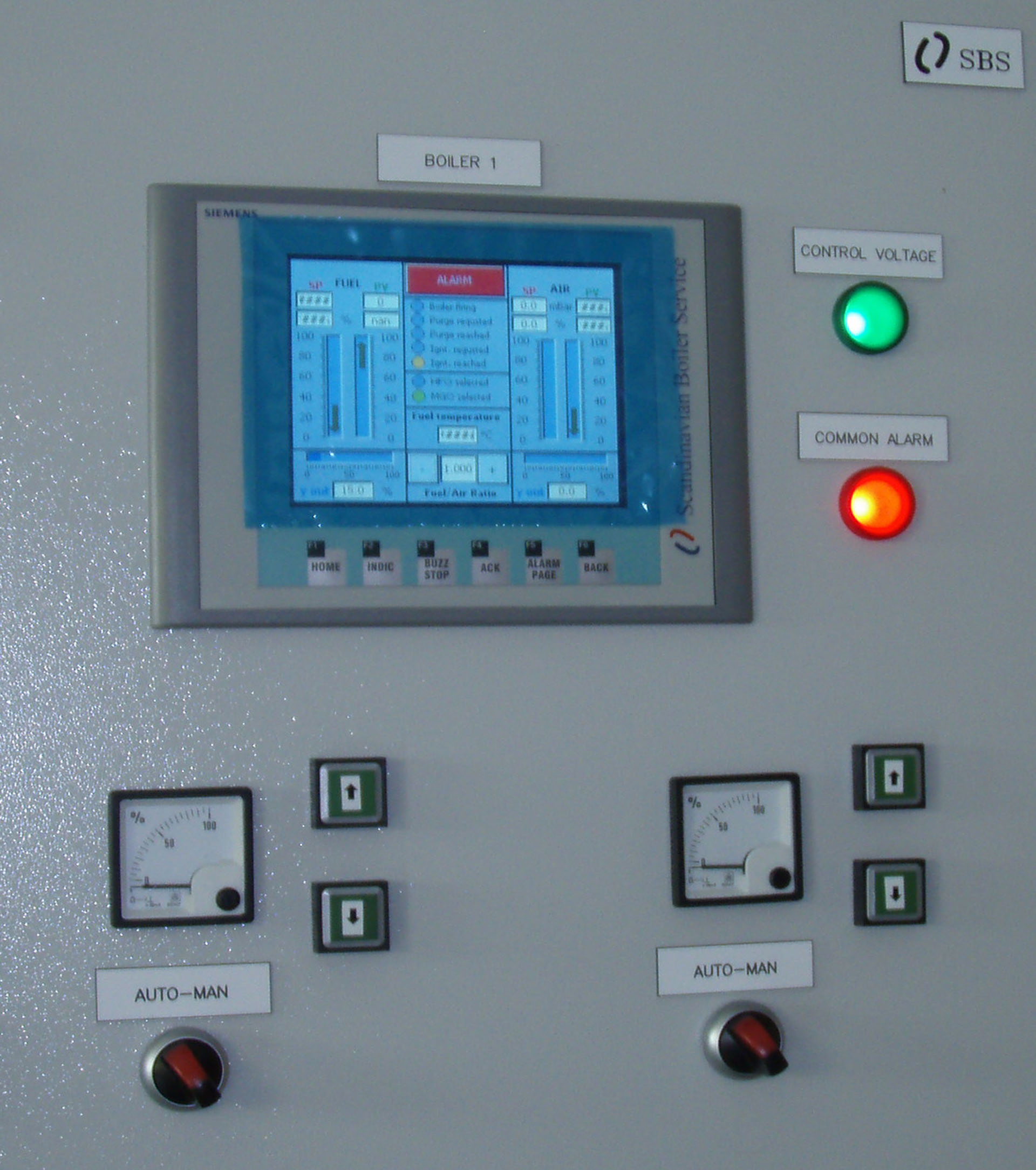
SBS-ACC-1B
SBS ACC 1B, Automatic Combustion Control One Boilers
Solutions based on the Automatic Combustion Controller ensures that systems which are not designed to run on dual fuel (HFO & LS MGO) have additional Fuel/Air curve for the MGO operation, ensuring optimum performance on both fuels. This is mainly used when present controllers are obsolete and this is installed as retrofit ensuring availability of spare parts in future.
Combustion Control System Description
A fuel-air metering control system is essential for efficient combustion in boilers, furnaces, and other large fuel-fired heating processed. These systems vary in complexity from the simple metered approach to the complex cross-limiting system, which is used to ensure safe firing during load changes.
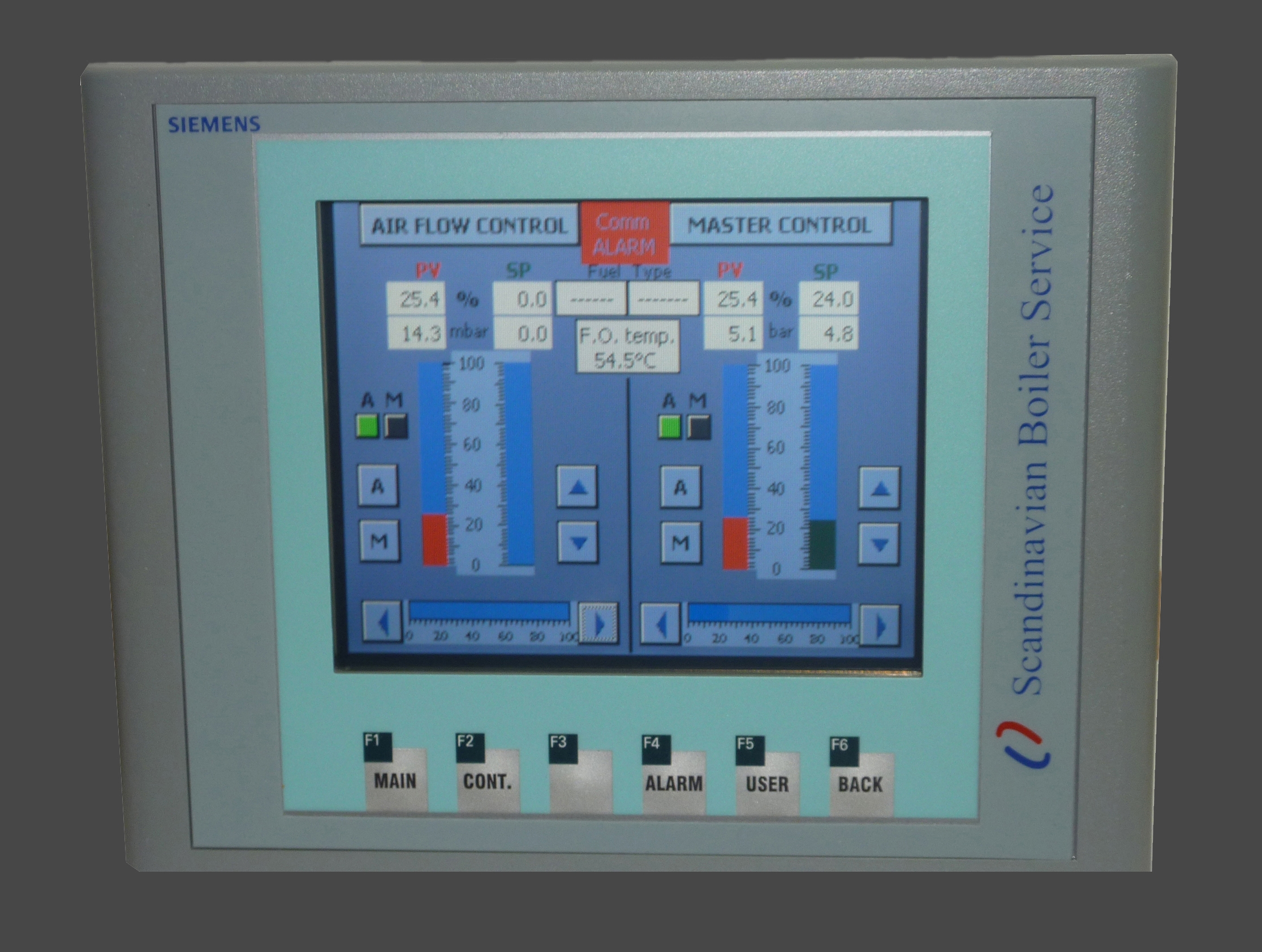
SBS-ACC-1B is build on SIEMENS S7-313C PLC and SIEMENS KTP 600DP Basic Touch screen hardware platform and SIEMENS S-7 programming software. All calculations in software are done using representation of analogue input in %. Physical unit of measurement are fused for indication purposes only. F.O flow feedback signal can be of Analogue current (4-20mA) Flow meter or Press (indirect flow measurement) signal and Tacho (frequency) signal selectable in system configuration.
It comprises of following functions:
– Fuel flow controller
– Air flow controller
– Ignition, Purge, FO recirculation & Burner firing positions selection over digital inputs, parameters for each mode configurable over HMI
– 2 F/A curves (switching via fuel selection Digital inputs )
– F/A Ratio control
– Fuel temperature monitoring (different set points for MGO/HFO, activated with F.O. Type selection)
– Alarming and registration of alarm events in Alarm History
– Fuel & Air Controller Trends
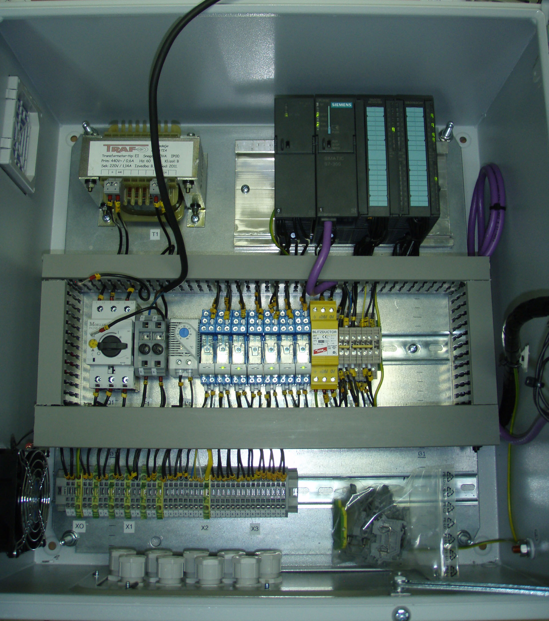
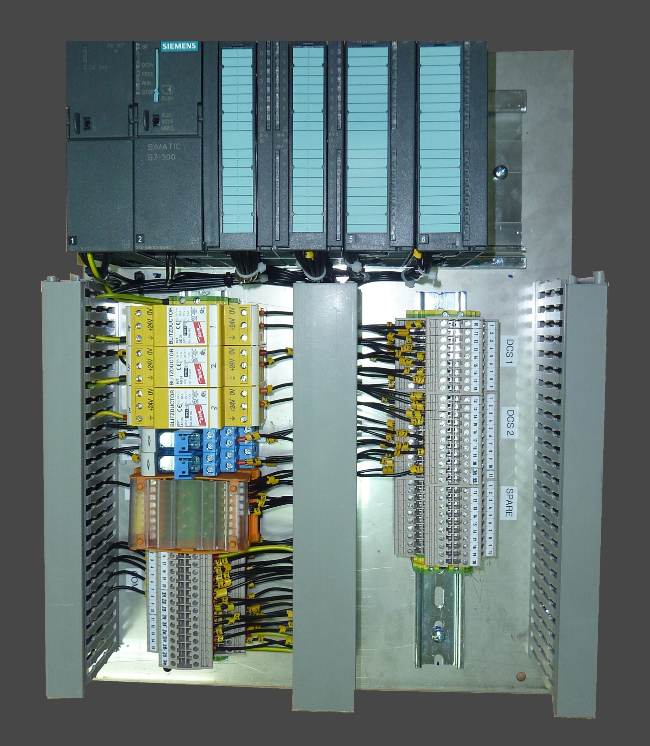
SBS-ACC-3B
SBS ACC 3B, Automatic Combustion Control Three Boilers
Same as ACC-1B but for boilers with up to 3 burners installed on 1 boiler. These are very complex systems and we managed to offer retrofit solution for obsolete Gaudelius & Shimadzu controllers, which are expensive and hard to get.
Combustion Control System Description
A fuel-air metering control system is essential for efficient combustion in boilers, furnaces, and other large fuel-fired heating processed. These systems vary in complexity from the simple metered approach to the complex cross-limiting system, which is used to ensure safe firing during load changes.
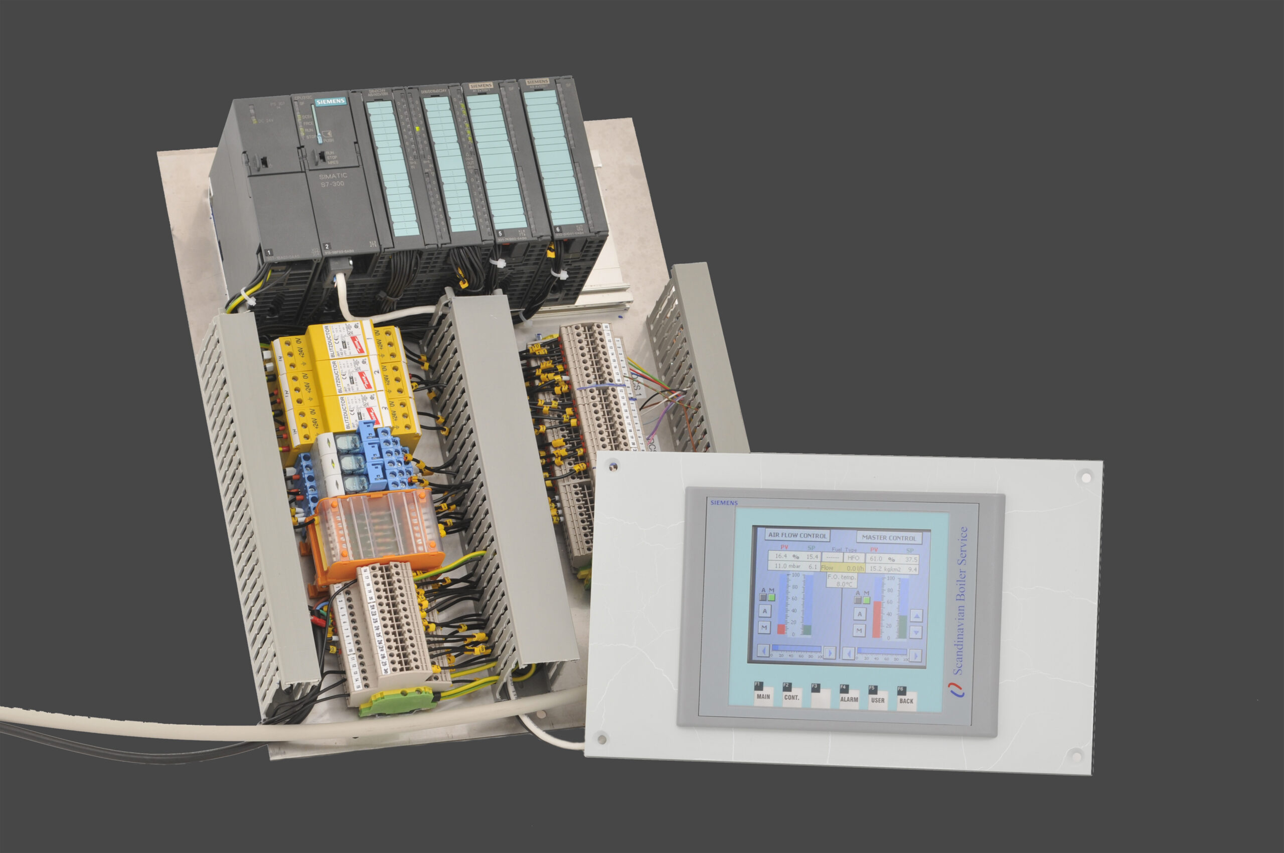
SBS-ACC-3B is device to control fuel oil and combustion air for optimum combustion, so that steam pressure may be kept at the set pressure at all time for required steam flow. System is build on SIEMENS S7-313C PLC, SIEMENS analogue input module SM331 2xAI, SIEMENS analogy output module SM332 4xAO, and SIEMENS KTP 600DP Basic Touch screen hardware platform and SIEMENS STEP7 programming software.
All calculations in software are done using representation of analogue input in %. Physical unit of measurement are fused for indication purposes only. F.O flow feedback signal can be of Analogue current (4-20mA) Flow meter or Press (indirect flow measurement) signal and Tacho (frequency) signal selectable in system configuration.
It comprises of following functions:
– Fuel flow controller
– Air flow controller
– Ignition, Purge, FO recirculation & Burner firing positions selection over digital inputs, parameters for each mode configurable over HMI
– 2 F/A curves (switching via fuel selection Digital inputs )
– F/A Ratio control
– Fuel temperature monitoring (different set points for MGO/HFO, activated with F.O. Type selection)
– Alarming
DOWNLOAD OUR BROCHURES
Learn more about SBS products and services in our products and services brochures.
Projects & Retrofits
Waste Heat Recovery Economizer
SBS Promo BBMS UNISAB II Retrofit
SBS Promo BBMS Volcano Retrofit
OUR WORKS
Our works and results speak volumes of our proficiency and commitment to our customers at all times. We take pride in our adeptness to deliver quality works in a timely manner. Explore a few of our past projects and we hope maybe one day, your ship will be a part of our story!

SPEAK TO OUR EXPERTS
With a network of global offices, SBS is always ready to answer the call of duty from our clients worldwide. We would love to hear from you, be it a service call or general enquiries.